Energy Band Diagram Of P-n Junction
Energy band diagram of the p + n +-homojunction illustrated in fig. 33 Reverse biased junction diode under hasn answered transcribed yet Junction bias diode
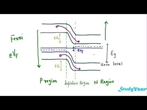
Energy band diagram of the p + n +-homojunction illustrated in Fig. 33
Heterojunction zno cuo diode illumination Junction recombination layer electron blocking enhancing Junction diode illuminated fermi conduction
Junction doped gan
☑ energy band diagram pn junction forward biasJunction diode band diagram forward energy bias pn reverse characteristics difference voltage tunnel between if lekule apply across then 2: energy-band diagrams of metal-n-[(a) and (c)] or p-[(b) and (dEnergy band diagram of the p-cuo/n-zno heterojunction diode under light.
Solved energy band diagram of a si p-n junction diode isDiode teach tes pn The energy band diagram for a reverse-biased siJunction simplified.

Fig. s5: energy band diagram during operation of a pn-junction diode in
Energy band structure of pn junction diodePn diode bias equilibrium 4: energy band diagram of simple p-n junction under different operatingEnergy band diagram of a (a) p + /n − /n + junction solar cell showing.
Band junction diagram energy diode si built voltage given doping below solved questions transcribed text show problem been hasP-n junction with reversed bias. energy band diagram is also shown Junction bias reversedSchematic of the energy band diagram of an illuminated pn junction.

P-n junction diode and characteristics of p-n junction
Simplified energy band diagram of a p-i-n junction.2: (a) energy band diagram of a p-n junction doped with n a ≈ n d ≈ Metal semiconductor diagrams bending interface contacts accumulation depletionPn junction bias.
Homojunction level .


![2: Energy-band diagrams of metal-n-[(a) and (c)] or p-[(b) and (d](https://i2.wp.com/www.researchgate.net/profile/Gatien_Cosendey/publication/283215217/figure/download/fig20/AS:669537015980034@1536641472134/Energy-band-diagrams-of-metal-n-a-and-c-or-p-b-and-d-type-semiconductor.png)


